4. Wiring
4.1. Wiring Precautions
When performing wiring operations, the following requirements must be strictly adhered to:
Note

Name:Warning
Note:
Do not touch the joint module components inside the arm base, to avoid the risk of electric shock.
External wiring work must only be performed by trained and authorized qualified engineers.
Check the voltage level of the equipment before powering on, otherwise it may cause personal injury and equipment damage.
To ensure safety, the equipment must be reliably grounded.
Do not connect the power input to any terminals other than the power connector, otherwise the product may be damaged.
The input voltage applied to all terminals must strictly not exceed the allowable range.
Before applying power, ensure that the wiring sequence is correct, the connections are secure, and the insulation is reliable; otherwise, the product may be damaged.
4.2. System Wiring
The humanoid robotic armART7-R7 has four configurations: Configuration 1 is single-arm, Configuration 2 is single-arm+ controller, Configuration 3 is dual-arm, Configuration 4 is dual-arm+ controller+ splitter. Its wiring diagrams are shown in Figures 4-1, 4-2, 4-3 and 4-4.
The power supply voltage of the humanoid robotic arm ART7-R7 is DC48V, and the power supply voltage of the controller and the splitter is DC24V, as shown in Figures 4-5 and 4-6.
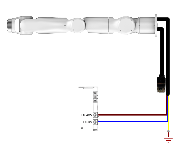
Figure 4-1 Configuration 1 Wiring Diagram

Figure 4-2 Configuration 2 Wiring Diagram
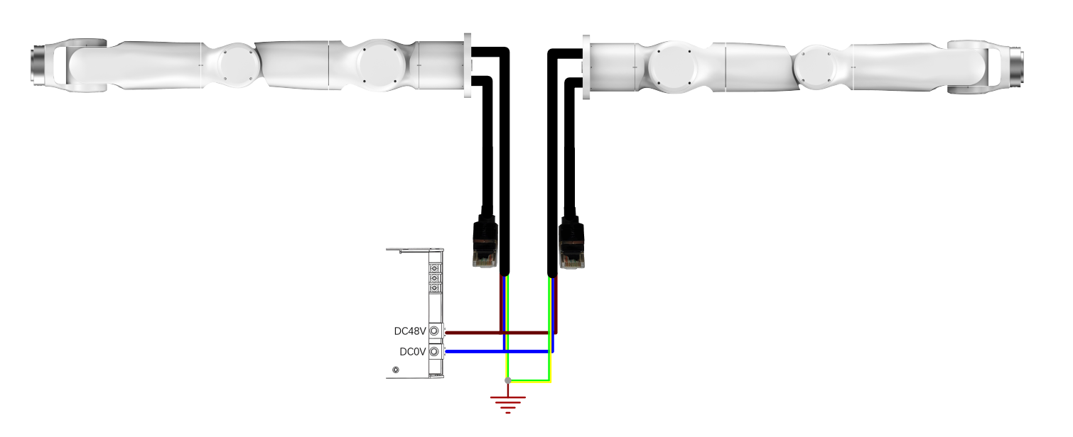
Figure 4-3 Configuration 3 Wiring Diagram

Figure 4-4 Configuration 4 Wiring Diagram
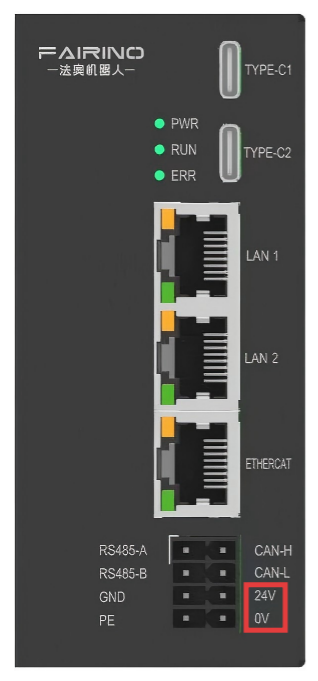
Figure 4-5 Controller Wiring Location
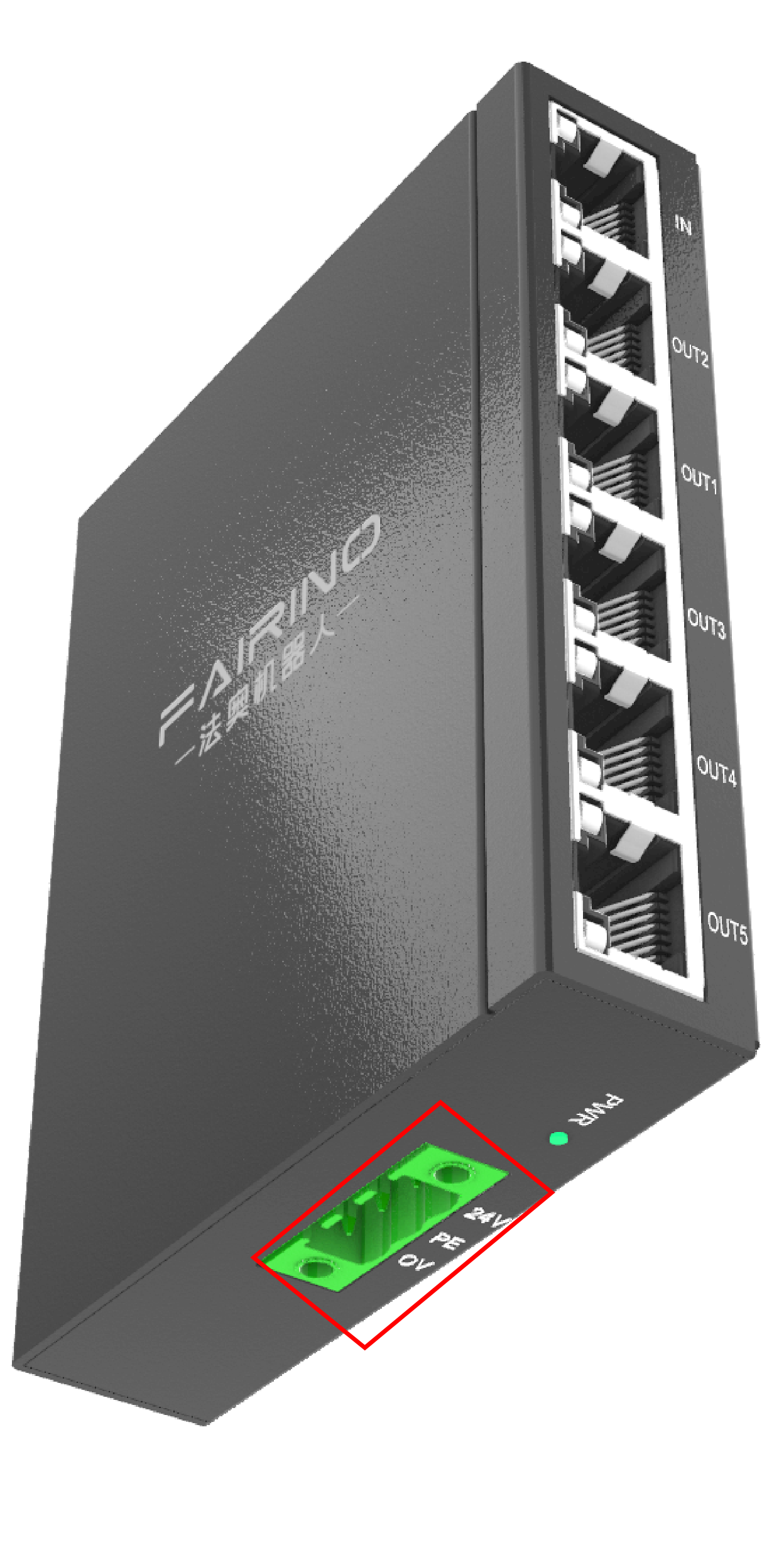
Figure 3-6 Splitter wiring position
4.3. Host PC Debugging Wiring
When debugging the robotic arm, connect the host computer and the controller using an Ethernet cable. As shown in Figure 4-7.
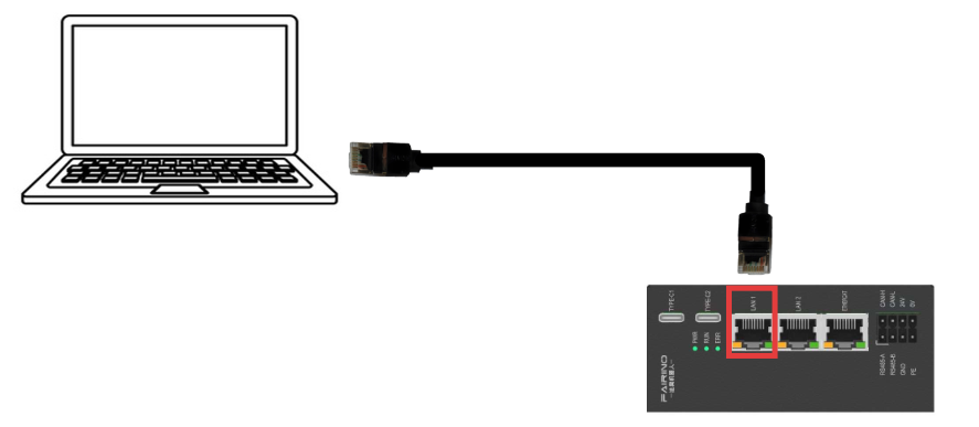
Figure 4-7 Wiring Diagram of Host Computer and Controller
Note

Name:Note
Note:
Please provide your own power supply for 24V and 48V.
Please provide your own Ethernet cable for host computer debugging.
Please provide your own network cable between the controller and the splitter.