2. Unboxing, Handling, Installation, and Activation Instructions
2.1. Unboxing
The humanoid robotic arm ART3-R7 has four configurations: Configuration 1 is a single arm, Configuration 2 is a single arm plus controller, Configuration 3 is dual arms, and Configuration 4 is dual arms plus controller plus brancher. As shown in Figure 2-1, 2-2, 2-3 and 2-4. After receiving the goods, please confirm the packing list.
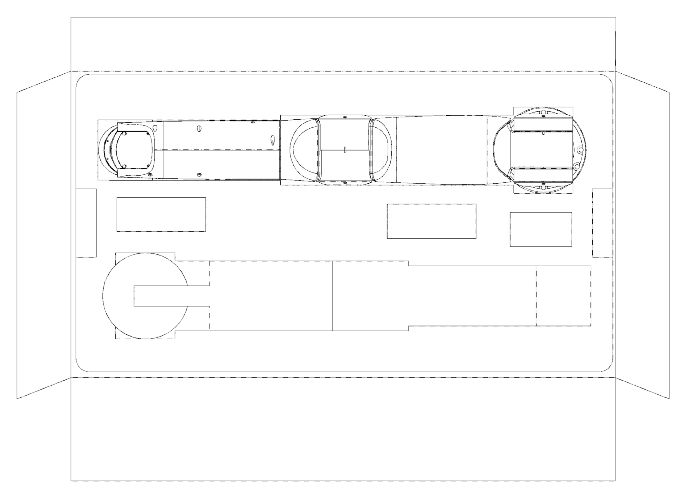
Figure 2-1 Configuration 1 Single-arm
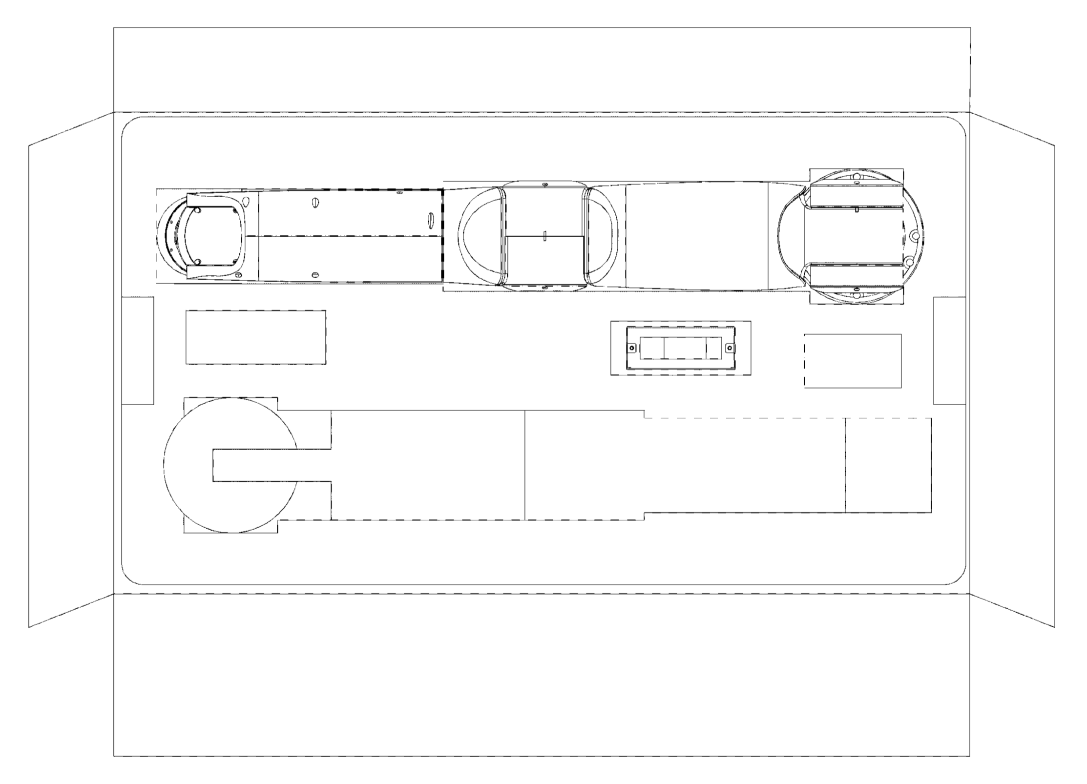
Figure 2-2 Configuration 2: Single Arm and Controller
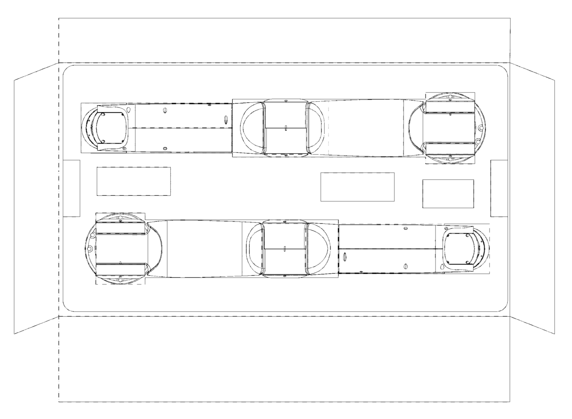
Figure 2-3 Configuration 3 Dual-arm
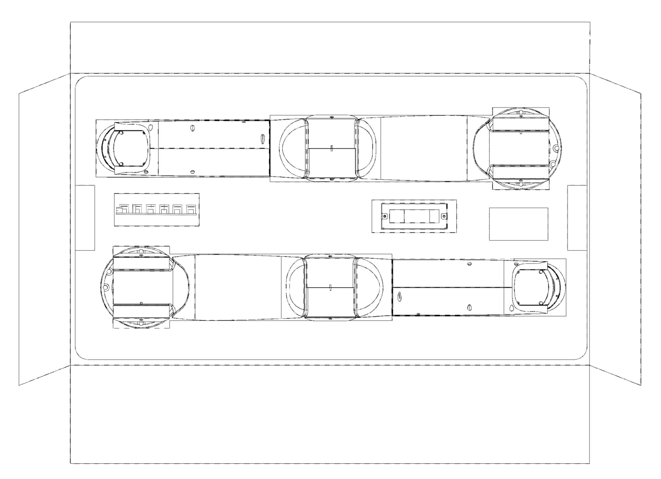
Figure 2-4 Configuration 4: Dual Arms, Controller, and Brancher
2.2. Handling
Note

Name: Danger
Instructions:
Please set up a safety barrier around the robot arm, which should be not easy to climb over and mobile. Otherwise, workers may enter the area when the robot arm is in motion, leading to personal injury and equipment damage.
Please clearly mark the robot arm operation area.
Note

Name: Warning
Instructions:
Lifting arms must be operated by personnel holding the corresponding operation qualification certificate or authorized by the company. Otherwise, the lifting arm may fall during handling, causing an accident.
After installing the robotic arm, ensure that when the arm is fully extended, the wrist tool or workpiece tip does not touch the wall or safety barrier. Otherwise, it may cause injury to personnel or damage to the equipment.
The robotic arm must be securely fixed before power is applied and the arm is started. Otherwise, there is a risk of the arm tipping over, which may cause injury to personnel and damage to the equipment.
Do not operate the robotic arm if parts are missing or damaged, as incorrect movements of the robotic arm may cause injury to personnel and damage to the equipment.
During transportation, avoid excessive vibration and impact. Otherwise, it will affect the performance of the robotic arm.
The humanoid robotic arm ART3-R7 product (including packaging) has a total weight of approximately 12-20 kg, and needs to be lifted by multiple people. It is not recommended for single-person operation to avoid accidents. Before long-distance transportation, adjust the robotic arm to the specified packing position and transport it after using the dedicated carton box.
2.3. Install and fix
2.3.1. Ontology Installation and Fixation
The base size of the humanoid robotic arm ART3-R7 is shown in Figure 2-5.
The robot arm base has six mounting holes. The recommended screw specifications for fixing the robot arm are shown in Table 2-1.
Table 2-1 Recommended Screw Specifications for Fixing the Robotic Arm
Installation |
|
Screw Specification |
Hexagon head screw M6×30 (recommended GB/T 3098.1 12.9 grade) |
Positioning pin specification |
Ø5×20 |
Screw Tightening Torque |
≥10 N·m |
Number of screws |
4 |
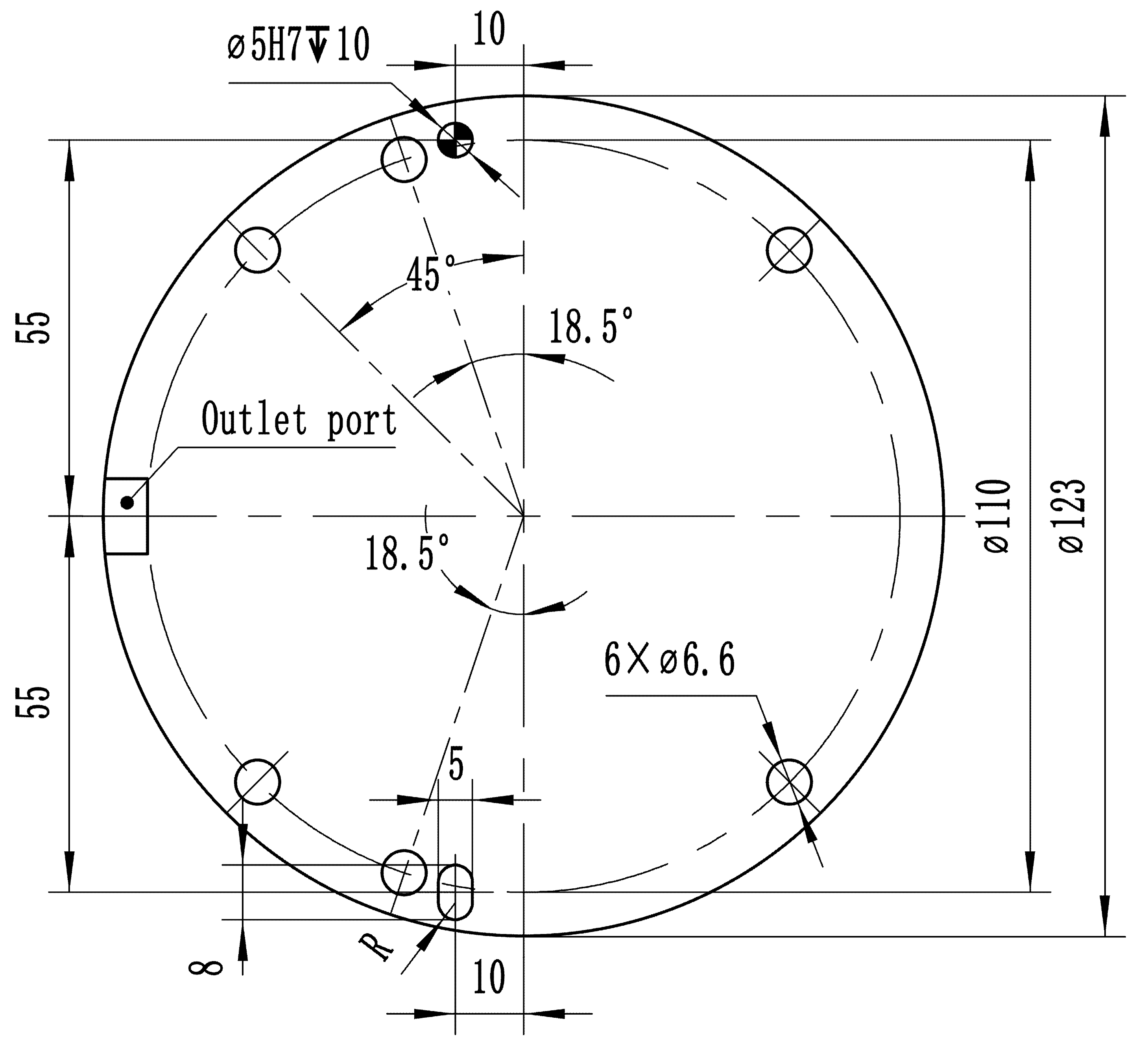
Figure 2-5 Base Mounting Dimensions
2.3.2. Controller and brancher
The controller has a dimension of 100mm×80mm×40mm, as shown in Figure 2-6. The distributor has a dimension of 125mm×81.25mm, as shown in Figure 2-7.
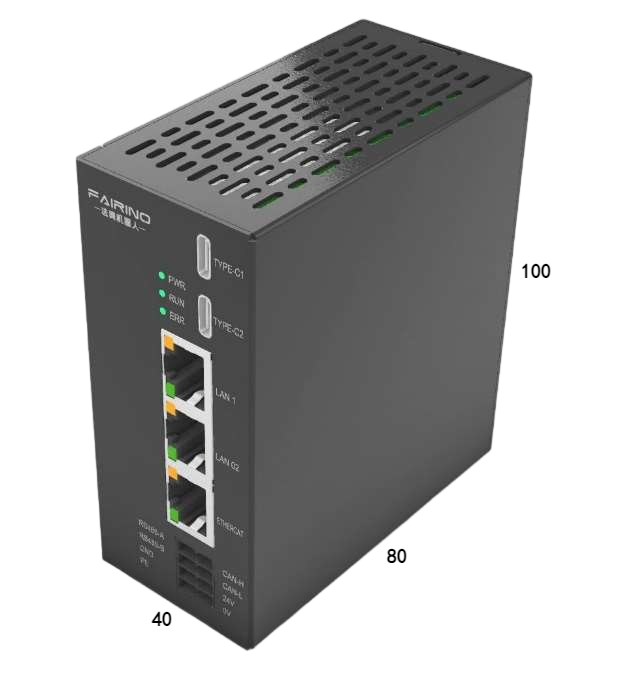
Figure 2-6 Controller Outline Diagram
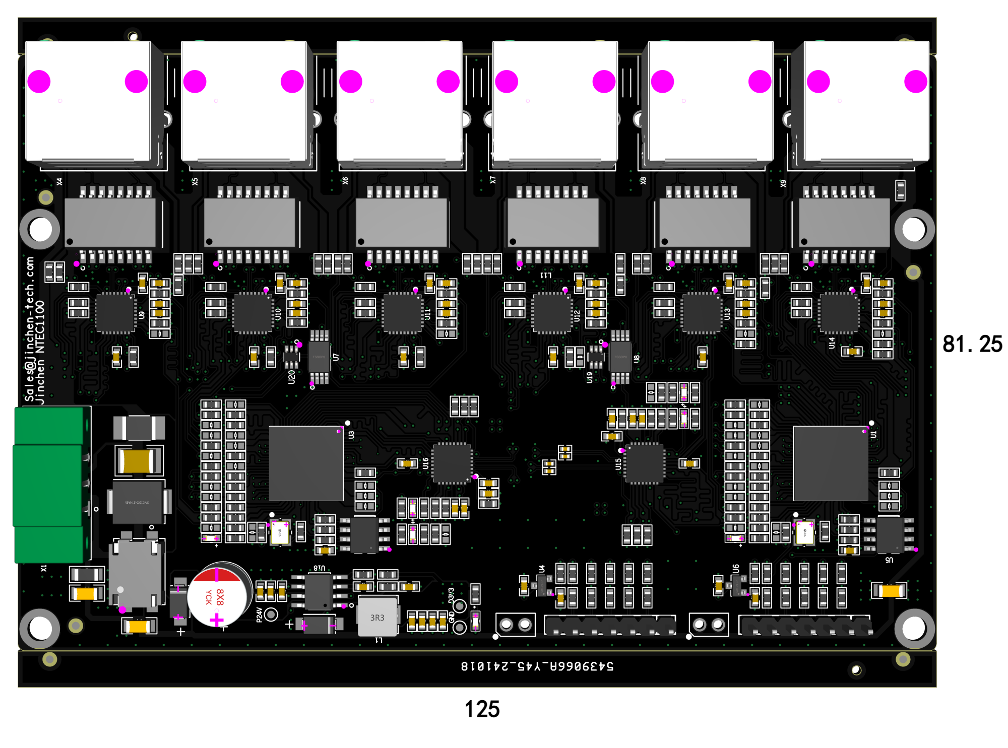
Figure 2-7 Schematic of the Brancher
2.4. Storage Location and Usage Environment
2.4.1. Storage place
The humanoid robotic arm ART3-R7 should be stored in an environment without condensation, at a temperature between -25~60℃.
2.4.2. Operating Environment
The location where the robotic arm is installed needs to meet the following conditions:
When the robotic arm is operating, the surrounding temperature should be within 0°C to 45°C;
Low humidity, relatively dry (operating humidity 90% RH, no condensation);
Not subject to significant impact and vibration;
Stay away from dust, powder, metal dust, corrosive gases, flammable gases, oil mist, etc.;
Stay away from strong magnetic fields, away from electrical interference sources, etc.;
The environmental temperature conditions are only applicable for the robotic arm. If you need to use it in places that do not meet the above conditions, please consult our company.
2.5. Enable
Before installing and using the product, the customer must conduct a comprehensive safety assessment for the specific application scenario, focusing on residual risk factors, and perform the corresponding security configurations for the software and hardware according to this manual. When starting the robotic arm for the first time, closely observe its motion space to ensure there are no interferences or obstacles.
Before using the robotic arm, confirm that the robotic arm’s zero position is consistent with the posture shown in Figure 2-8 and Figure 2-9. If the robotic arm has not moved to the position shown in the diagram, please consult our company.
The robotic arm has been zero-point calibrated at the factory, so zero-point calibration is not required during daily operations. However, zero-point calibration is needed after the following situations occur.
Replaced the joint driver or the robotic arm joint;
Reinstall the system or replace the controller;
After a severe collision.
The zero-point calibration positions of each axis of the manipulator are shown in Figure 2-9.
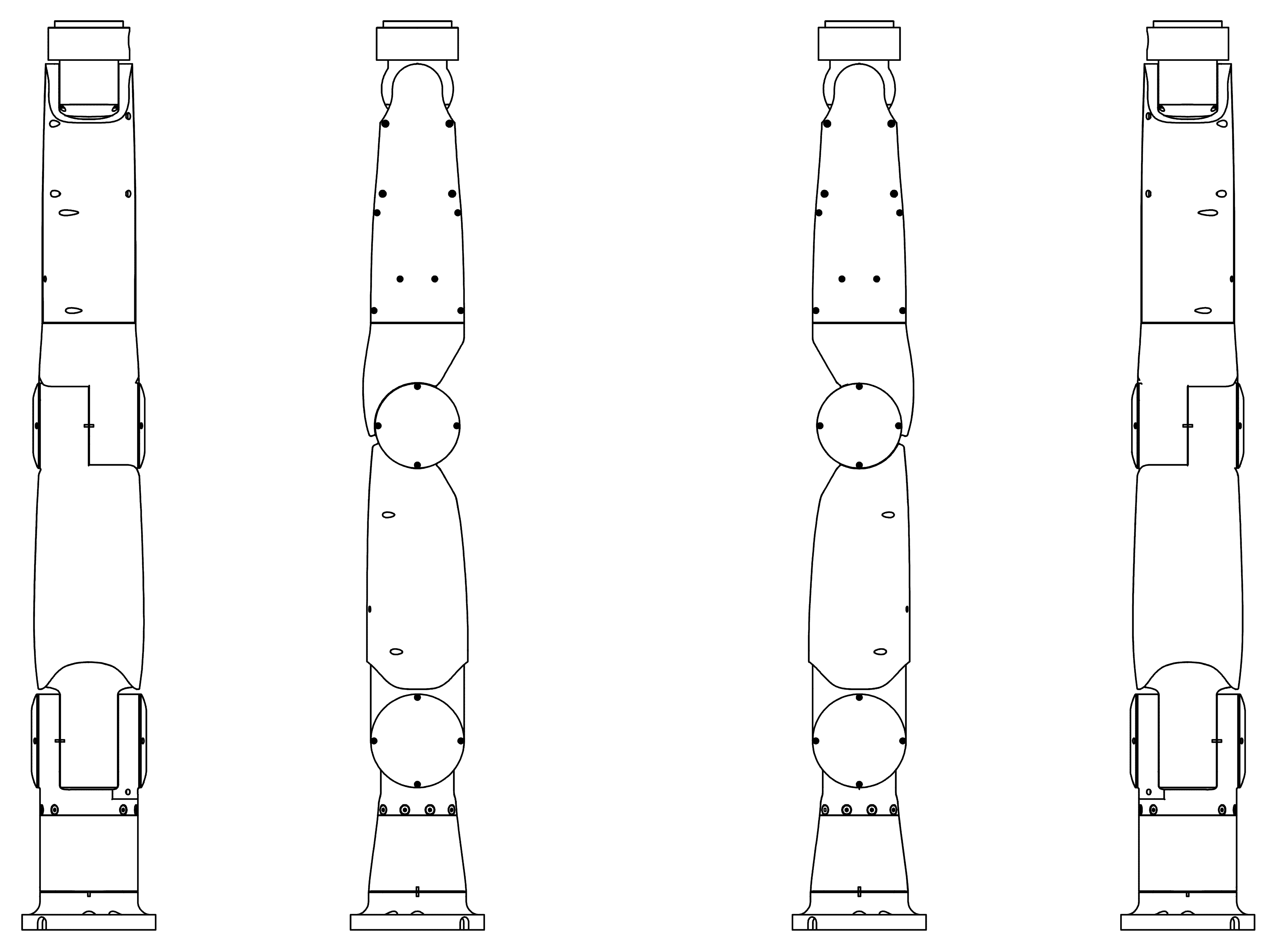
Figure 2-8 Left Arm Zero Posture, Right Arm Zero Posture
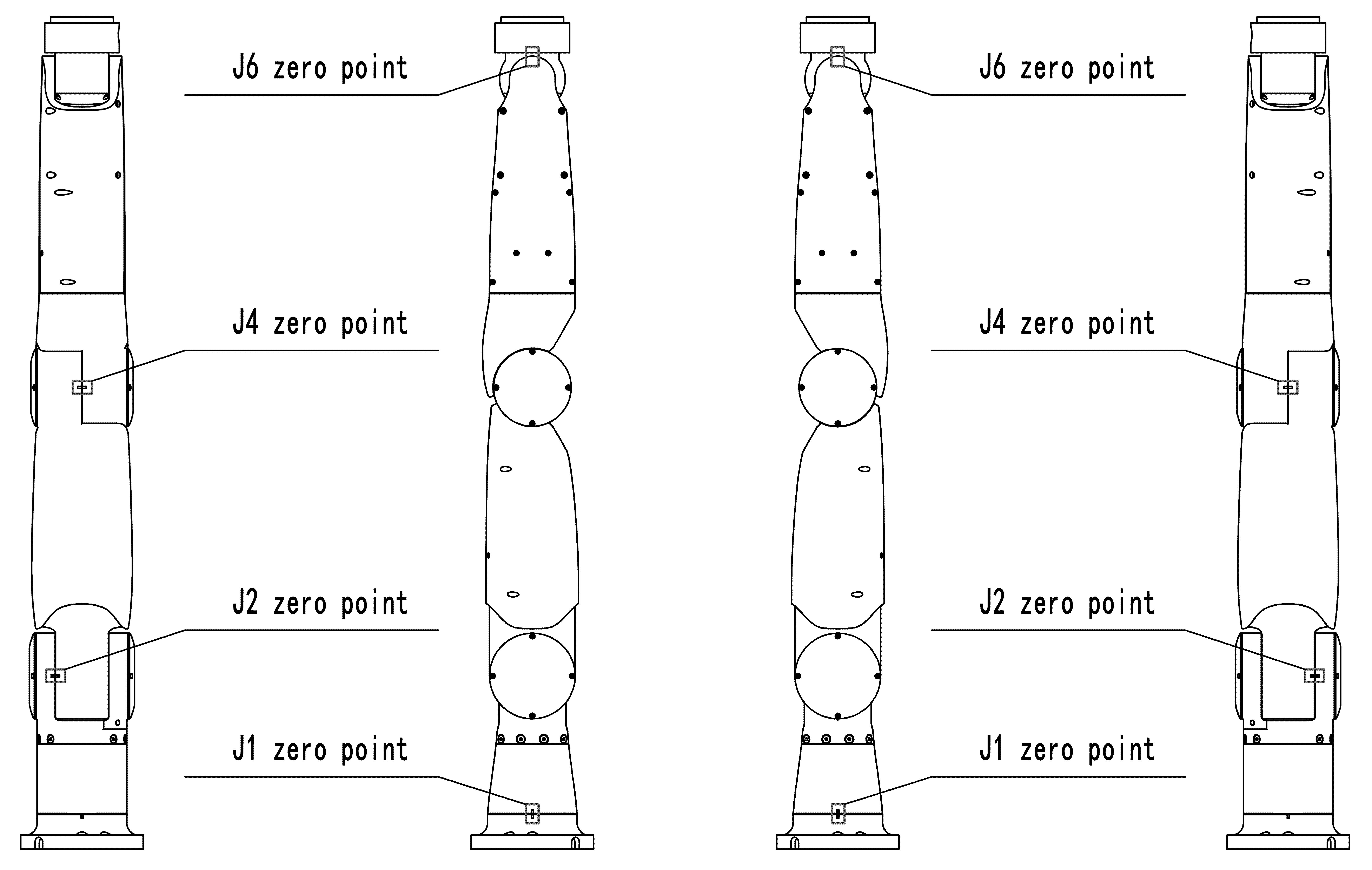
Figure 2-9 Left Arm Zero Position Calibration, Right Arm Zero Position Calibration