3. Product Introduction
3.1. Product dimensions
The outer dimensions of the left and right arms are both 836.5mm × 123mm × 123mm, as shown in Figure 3-1 and 3-2.

Figure 3-1 Left Arm External Dimensions

Figure 3-2 Right Arm External Dimensions
3.2. Nameplate information
The nameplate information of a single arm and the packaging box is shown in Figure 3-3 and 3-4.
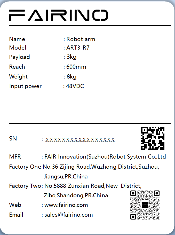
Figure 3-3 Configuration 1 Single-arm Nameplate Information
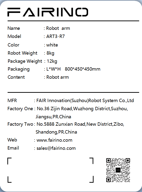
Figure 3-4 Configuration One - Carton Nameplate Information
Configuration two, the nameplate information of the single arm plus controller and the packaging box is shown in Figure 3-5 and 3-6.
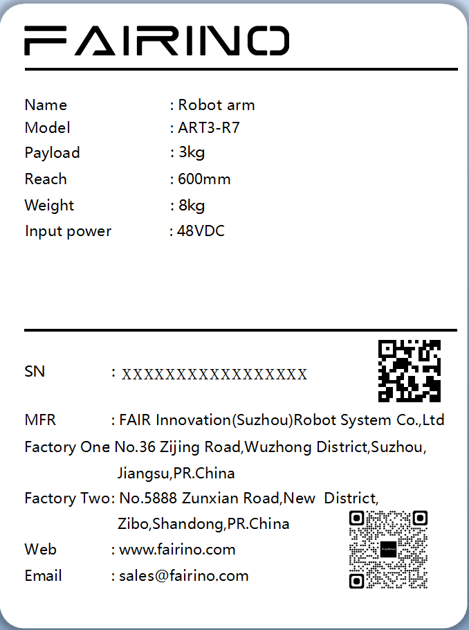
Figure 3-5 Configuration 2 Single-arm Nameplate Information
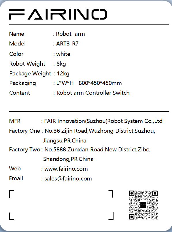
Figure 3-6 Configuration 2 - Carton Label Information
The nameplate information of the three-arm configuration and the packaging box is shown in Figure 3-7, 3-8, and 3-9.
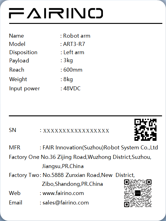
Figure 3-7 Configuration 3 - Left Arm Nameplate Information
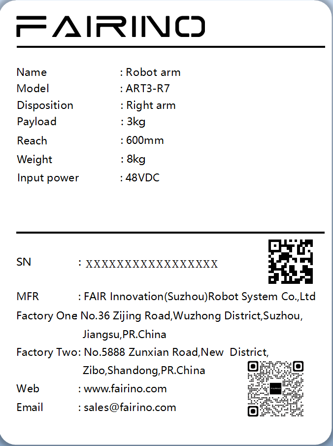
Figure 3-8 Configuration 3 Right Arm Nameplate Information

Figure 3-9 Configuration 3 - Packaging Box Nameplate Information
The nameplate information of the four-arm configuration, controller, coupler, and packaging box is shown in Figure 3-10, 3-11, and 3-12.
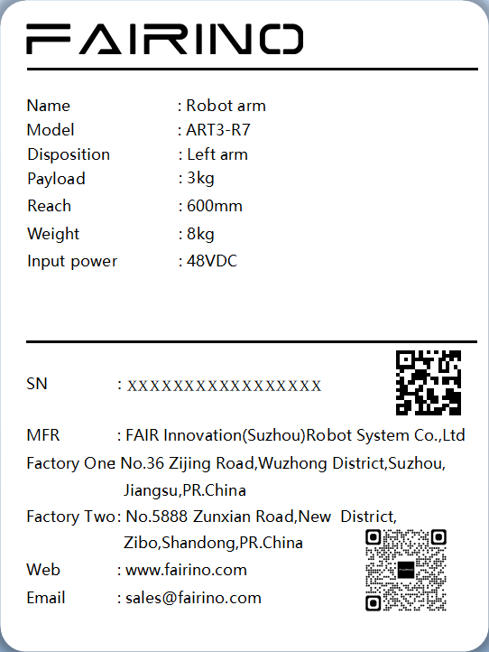
Figure 3-10 Configuration 4 Left Arm Nameplate Information
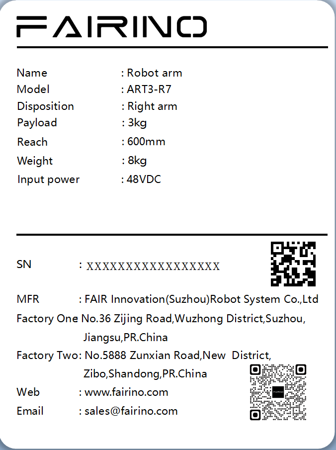
Figure 3-11 Right Arm Nameplate Information
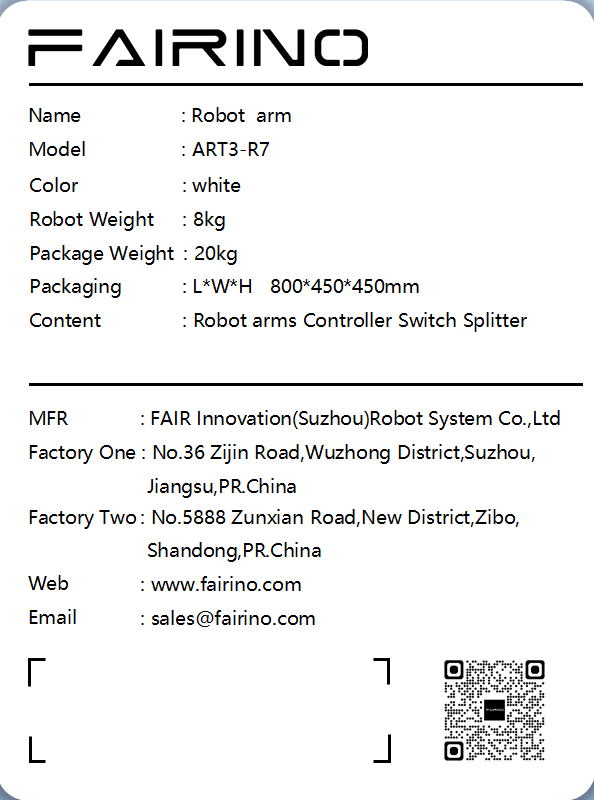
Figure 3-12 Configuration 4 Packaging Box Nameplate Information
3.3. Technical Specifications
The technical specifications of the robotic arm are shown in Table 3-1.
Table 3-1 Technical Parameters
Parameter Type |
Specific parameters |
Model Parameters |
ART3-R7 |
Payload |
Single-arm 3kg |
Effective working range |
600 mm |
Degrees of freedom |
7 degrees of rotational freedom |
Range of motion |
Axis 1: ±175° |
Range of motion |
2-axis: ±93° |
Range of motion |
3-axis: ±175° |
Range of motion |
4-axis: 0-120° |
Range of motion |
5-axis: ±175° |
Range of motion |
6-axis: ±75° |
Range of motion |
7-axis: ±175° |
Joint velocity |
Axis 1-2 ≥150°/s, Axis 3-7 ≥180°/s |
Noise |
<65dB |
Installation direction |
Any direction |
Repositioning accuracy |
±0.1mm |
Overall unit quality |
About 8 kg |
3.4. Joint Definition
The joints of the left and right arms are defined as shown in Figure 3-13 and 3-14.
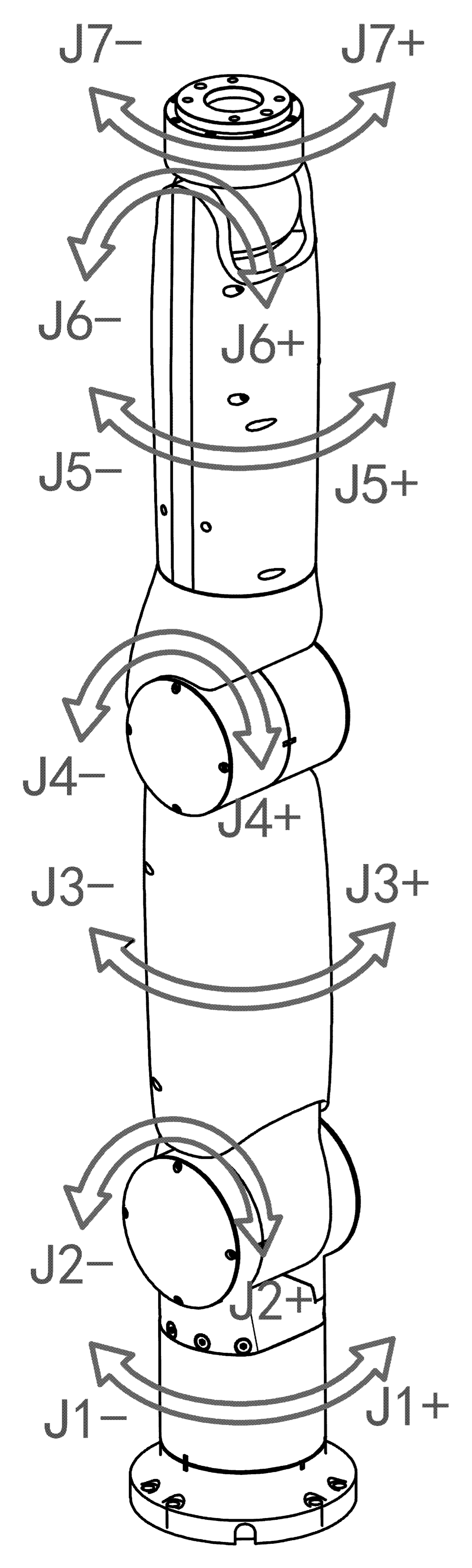
Figure 3-13 Left Arm Joint Definition
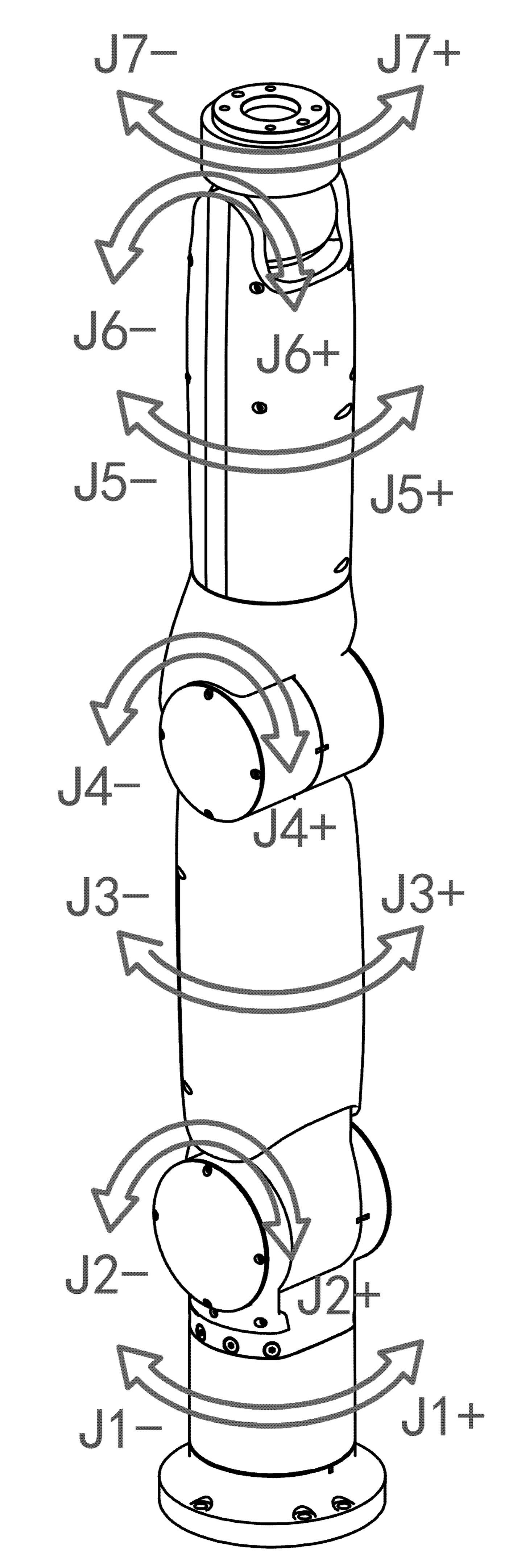
Figure 3-14 Right Arm Joint Definition
3.5. Range of motion
The motion range of the manipulator is shown in Figure 3-15.
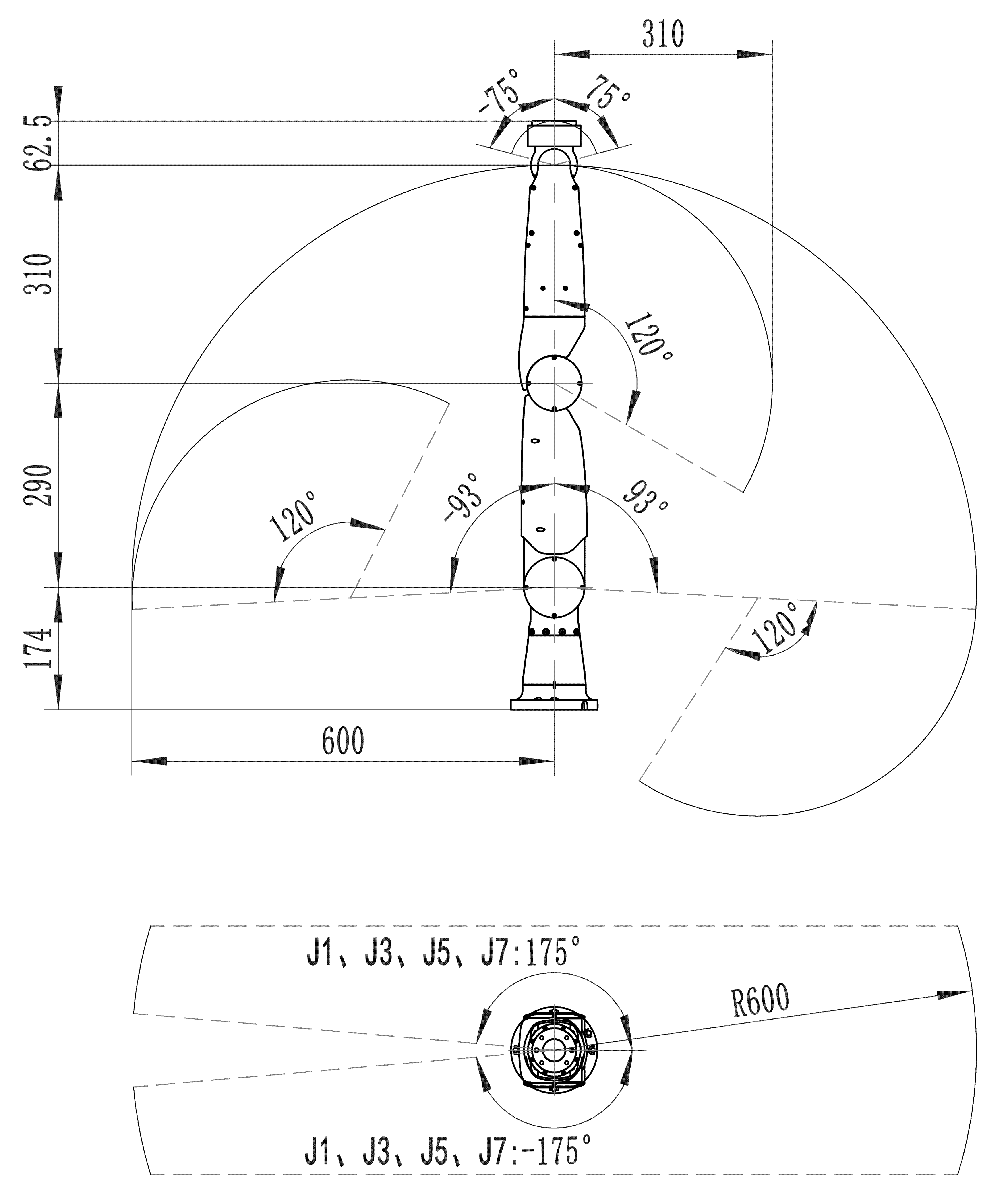
Figure 3-15 Manipulator’s Working Range
3.6. DH Parameters and Coordinate System
The DH parameters of the left arm are shown in Table 3-2 and Figure 3-16.
Table 3-2 DH Parameters of the Left Arm
joint_i |
θi |
di/mm |
AI |
αi/rad |
1 |
0 |
174 |
0 |
-π/2 |
2 |
0 |
0 |
0 |
pi/2 |
3 |
0 |
290 |
0 |
-π/2 |
4 |
0 |
0 |
0 |
pi/2 |
5 |
0 |
310 |
0 |
-π/2 |
6 |
0 |
0 |
0 |
pi/2 |
7 |
0 |
62.5 |
0 |
0 |
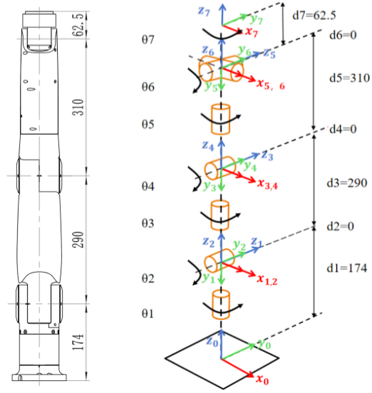
Figure 3-16 Left Arm Coordinate System
The DH parameters of the right arm are shown in Table 3-3 and Figure 3-17.
Table 3-3 Right Arm DH Parameters Table
joint_i |
θi |
di/mm |
AI |
αi/rad |
1 |
0 |
174 |
0 |
-π/2 |
2 |
0 |
0 |
0 |
pi/2 |
3 |
0 |
290 |
0 |
-π/2 |
4 |
0 |
0 |
0 |
pi/2 |
5 |
0 |
310 |
0 |
-π/2 |
6 |
0 |
0 |
0 |
pi/2 |
7 |
0 |
62.5 |
0 |
0 |
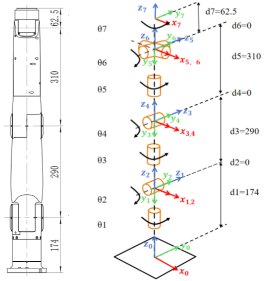
Figure 3-17 Right Arm Coordinate System
3.7. Tool flange size
The end-effector flange size is shown in Figure 3-18.
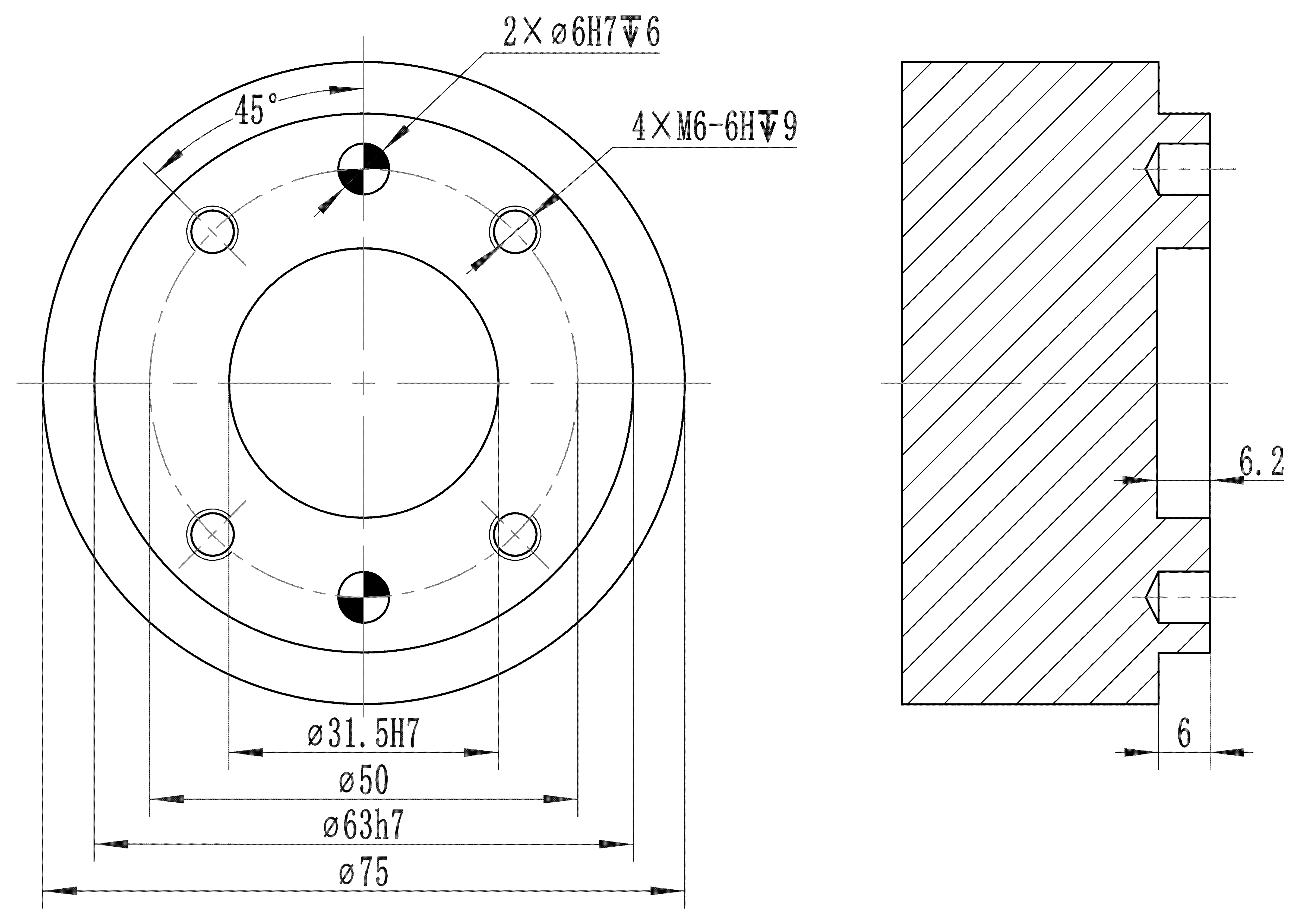
Figure 3-18 End Tool Flange Dimensions
3.8. Robot load curve (simulation)
3.8.1. Overview
The load curve describes the robot’s load capacity, helping users select appropriate models and assess the feasibility of the installed end-effector load.
3.8.2. Load curve
The load curves covered in this section are obtained from trajectory simulations of the ART3-R7 robot at different global operating speeds (30%, 50%, 80%, and 100%). Each load curve consists of two parts: “Full Performance” and “Extended Load Capacity,” as detailed below:
The “Full Performance” operating environment is defined as follows: friction compensation coefficients for all joints are set to 1; collision sensitivity levels for all joints are set to 10; the corresponding operating speed is configured via the Web interface; the default acceleration in Maintenance Mode is 360 deg/s²; and Dynamics 2.0 is enabled. Under this environment, the “Full Performance” segment of the payload curve accommodates the vast majority of motion trajectories.
If the end-effector load is within the “extended load capacity,” the “time-optimal mode” must be enabled while satisfying the acceleration limits, or the robot’s working range must be reduced.
3.8.2.1. Parameter Description
The robot’s rated payload depends on the center-of-gravity offset of the payload, defined as the distance between the center of the end flange and the center of gravity of the attached payload.
3.8.2.2. Load curve at 30% operating speed
At 30% of the global operating speed, the ART3-R7 robot model has a maximum payload capacity of 5 kg and a rated payload of 3 kg, as shown in the payload curve below. The payload curve is interpreted as follows:
ART3-R7 can carry a load of 3 kg or less at full performance, as shown by the “blue envelope.”
When the load is 3 kg to 5 kg, the extended load capacity (see the “red envelope curve”) allows the robot to operate in the following states:
① Enable “Time-Optimal Mode”; it is recommended to set the acceleration below 108 deg/s².
② Reduce the robot’s working range to avoid frequent impacts.
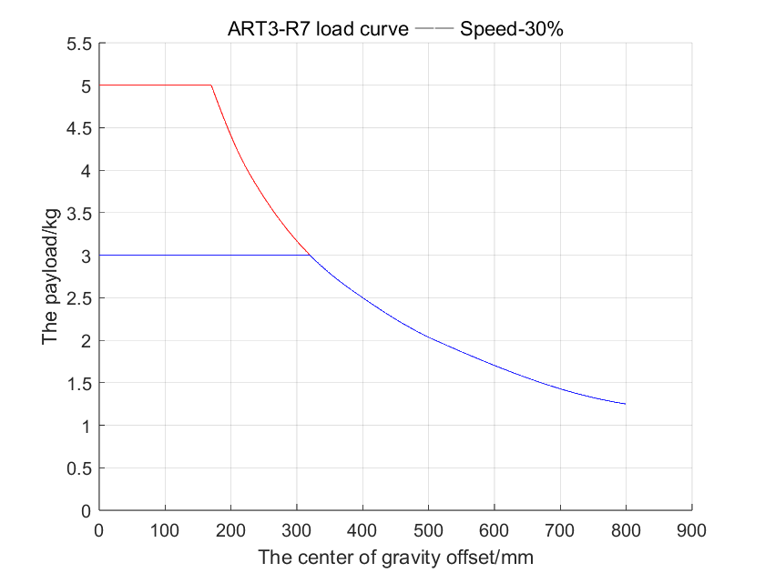
Figure 3-19 Load Curve—Global Operating Speed at 30%
3.8.2.3. Load curve at 50% operating speed
At 50% of the global operating speed, the ART3-R7 robot model has a maximum payload capacity of 5 kg and a rated payload of 3 kg, as shown in the payload curve below. The payload curve is interpreted as follows:
ART3-R7 can carry a load of 3 kg or less at full performance, as shown by the “blue envelope.”
When the load is 3 kg to 5 kg, the extended load capacity (see the “red envelope curve”) allows the robot to operate in the following states:
① Enable “Time-Optimal Mode”; it is recommended to set the acceleration below 180 deg/s².
② Reduce the robot’s working range to avoid frequent impacts.
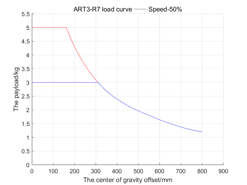
Figure 3-20 Load Curve—Global Operating Speed at 50%
3.8.2.4. Load curve at 80% operating speed
At 80% of the global operating speed, the ART3-R7 robot model has a maximum payload capacity of 5 kg and a rated payload of 3 kg; the payload curve is shown in the figure below. The payload curve is interpreted as follows:
ART3-R7 can carry a load of 3 kg or less at full performance, as shown by the “blue envelope.”
When the load is 3 kg to 5 kg, the extended load capacity (see the “red envelope curve”) allows the robot to operate in the following states:
① Enable “Time-Optimal Mode”; it is recommended to set the acceleration below 288 deg/s².
② Reduce the robot’s working range to avoid frequent impacts.
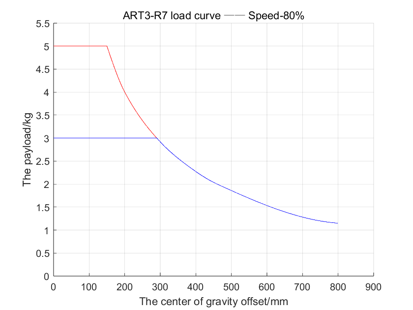
Figure 3-21 Load Curve—Global Operating Speed at 80%
3.8.2.5. Load curve at 100% operating speed
At 100% global operating speed, the maximum payload capacity of the ART3-R7 robot model is 5 kg, with a rated payload of 3 kg. The payload curve is shown below. The specific interpretation of the payload curve is as follows:
ART3-R7 can carry a load of 3 kg or less at full performance, as shown by the “blue envelope.”
When the load is 3 kg to 5 kg, the extended load capacity (see the “red envelope curve”) allows the robot to operate in the following states:
① Enable “Time-Optimal Mode”; it is recommended to set the acceleration below 360 deg/s².
② Reduce the robot’s working range to avoid frequent impacts.
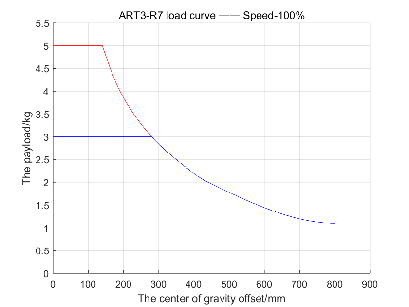
Figure 3-22 Load Curve—Global Operating Speed at 100%
3.9. Robot load curve (actual machine)
3.9.1. Overview
In robotics,load capacity usually refers to the maximum load that the end effector of a robot arm can withstand,including the weight of the end effector and additional loads。The manipulator load curve is used to describe the relationship between the end load’s center-of-gravity offset and the mass,and is one of the reference indicators for customers to select a manipulator type,which determines the application range and work efficiency of the robot arm。
3.9.2. Load curve
The load curves covered in this section are based on ART3-R7 global running speed of 100%, with speed feedforward function and T type speed enabled, and are obtained through actual machine testing by executing a specific trajectory. The load curves consist of two parts: “ full performance ” and “ extended load capacity ”, as follows:
“ The operating environment of full performance ” is: set the corresponding operating speed, the speed in maintenance mode is 150 deg/s, and the acceleration defaults to 300 deg/s2 。 In this environment, the “ full performance ” portion of the load curve adapts to the vast majority of operating trajectories。
If the end load is within “extended load capacity”, it is recommended to reduce the robot’s working range or lower the operating speed.
3.9.2.1. Parameter Description
The robot’s rated payload depends on the center-of-gravity offset of the payload, defined as the distance between the center of the end flange and the center of gravity of the attached payload.
3.9.2.2. ART3-R7负载曲线
ART3-R7 model robot’s maximum payload is 5kg, rated load is 3kg, as shown in load curve 1. The specific explanation of the load curve is as follows:
ART3-R7 can carry a load of 3 kg or less at full performance, as shown by the “blue envelope.”
When the load is 3 kg to 5 kg, the extended load capacity (see the “red envelope curve”) allows the robot to operate in the following states:
①It is recommended that the speed and acceleration be set below 150 deg/s and 300 deg/s2;
② Reduce the robot’s working range to avoid frequent impacts.
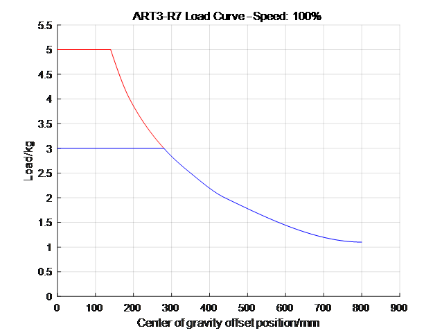
Chart 3-23 Load Curve—Global Running Speed100%